MLS Calibration
The task of mobile scanner calibration includes solving misalignment angles heading, roll and pitch for each scanner in a system. Misalignment issues are visible in the point cloud as differences between points of different drive paths and points of different scanners. The misalignment is more and more noticeable in the data the longer the distance is from the scanner. It has practically no effect on close-by objects, for which rather trajectory xyz inaccuracies dominate.
Potential objects for mobile scanner calibration are vertical planar surfaces, such as building walls, building corners and horizontal hard planar surfaces. A heading misalignment effects the xy location of a vertical surface or a building corner while roll and pitch effect the verticality of vertical surfaces as well as the elevation of horizontal surfaces in left/right (roll), forward/backward (pitch) direction. Other usable objects are vertical poles and overhead wires, but those objects have disadvantages, such as being off from vertical or varying diameters (poles) and possible movement (wires).
The tie line types used for calibration are Section lines on planar horizontal or vertical surfaces and Xy points , for example on building corners. More information about different tie line types can be found in section Tie line types.
Drive pattern
A good calibration side is an open space with hard surface ground and without disturbing objects such as cars, trees, etc. At least on one side there should be a larger building wall or another large vertical surface without many detailed structures.
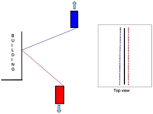
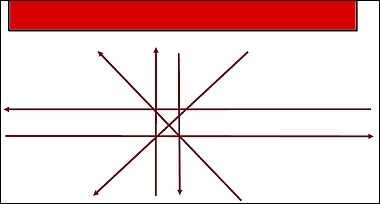
The calibration drive may includes two drive paths in opposite direction parallel to the vertical surface, two drive paths in opposite direction perpendicular to the vertical surface and (optionally) two diagonal drive paths towards or away from the vertical surface. Another option is to drive over an intersection of two road with at least two buildings next to the crossing, both roads in opposite directions. The two calibration drive pattern are illustrated below.
Only a suitable drive pattern for the appropriate scanner configuration ensures that all calibration parameters can be solved based on the laser data. The drive pattern described here are optimized for calibrating scanner systems that contain two scanners which are rotated horizontally by about 45 degree off from the driving direction. For any significantly different scanner configuration, the drive pattern must be adjusted accordingly.
Scan direction for solving Heading •mismatch visible at a longer distance from scanner •mismatch visible on vertical walls if scanned from different angles (preferable close to 45 degree) •mismatch visible on point-like objects (building corners, poles, etc.) |
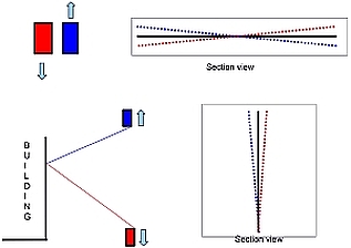
Scan direction for solving Roll •mismatch visible at a longer distance from scanner •mismatch visible on vertical walls that are leaning in the point cloud if scanned in left/right direction relative to the drive direction •mismatch visible as elevation difference on the ground |
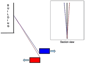
Scan direction for solving Pitch •mismatch visible at a longer distance from scanner •mismatch visible on vertical walls that are leaning in the point cloud if scanned in forward/backward direction relative to the drive direction •mismatch visible as elevation difference on the ground |
Drive pattern option 1, e.g. on a parking lot |
Drive pattern option 2, road crossing |

Processing steps
The processing of a calibration data set can be outlined with the following steps:
1. Generate trajectories with the GPS-IMU post-processing software of your system.
2. Generate a point cloud with system specific software using the last known calibration values.
3. Define a scanner system in TerraScan Settings that stores the lever arms from IMU to each scanner of your system.
4. Import trajectories into TerraScan. Assign the correct scanner system.
5. (Optional) Import the accuracy estimate file for the trajectory.
6. Import the laser cloud into TerraScan. In ideal case, you can load all points from the calibration drive into memory and thus, work on loaded points. Assign the scanner number during the import, e.g. based on the file or folder name. The scanner number for laser points must be the same as the scanner number in the scanner system definition. Point cloud and trajectories must be in the same coordinate system.
7. Save the laser points in LAS or TerraScan Fast Binary format which are able to store a scanner number for each laser point.
8. Split trajectories to create separate trajectory lines for each drive path.
9. Make sure that the drive path numbering of the laser points matches trajectory numbers (TerraScan Deduce using time command).
10. Remove unnecessary points from the point cloud, e.g. from stops, sharp turns or long range measurements.
11. Classify points on hard planar ground surface close to the trajectory lines (by centerline) and maybe point on building walls (by range above scanner).
12. Search tie lines of type Section lines on vertical walls.
13. Search tie lines of type Section lines on flat ground.
14. (Optional) Add more tie lines manually if the automatically found tie lines do not give a good result. This may be the case if the drive pattern was not optimal for the calibration task.
15. Run Find Tie Line Match and solve for heading, roll, and pitch for the whole data set. Separate scanners if your system contains multiple scanners.
16. Add the reported correction values to the correction values used when generating the point cloud in step 2.