Find Tie Line Match
 Find Tie Line Match tool analyzes the mismatch in the tie lines and searches correction values. The tool utilizes the feature-to-feature matching method described in Find match vs. Tie Lines.
In preparation of using this tool, you have to import trajectories into TerraScan and collect tie lines that are suited for solving the required parameters.
General procedure for solving and applying correction parameters:
1. Select the Find Tie Line Match tool.
This opens the Find Tie Line Match dialog:
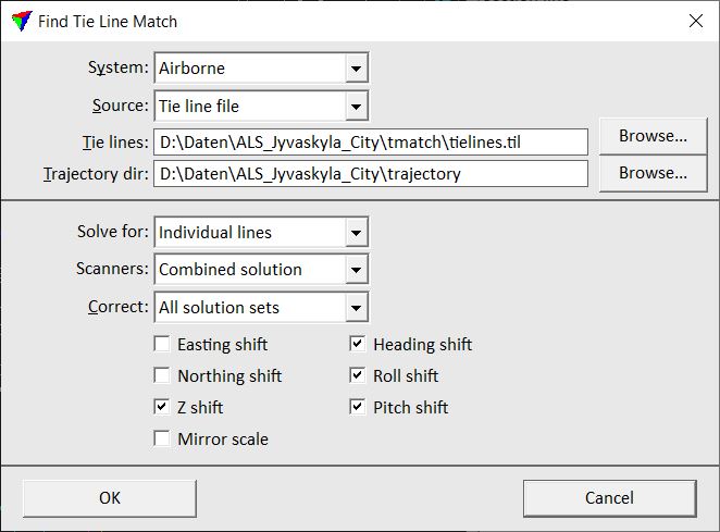
2. Define settings and click OK.
Setting |
Effect |
|---|---|
System |
Scanner system used for collecting the laser data: •Airborne - scanner with a line or zig-zag scan pattern. For scanners with any other scan pattern, Generic is the better choice, even if it is an airborne system scanner. •Generic - mobile system scanner, airborne system scanner with any other than line or zig-zag scan pattern. |
Source |
Source file for calculating the correction values: •Active tie lines - tie lines in an open Tie line window are used. •Tie line file - tie lines stored in a tie line file are used. |
Tie lines |
Path to the tie line file that is used for calculating the correction values. This is only active when Source is set to Tie line file. |
Trajectory dir |
Directory where the TerraScan trajectory files are stored. |
Solve for |
Type of solution to find: •Whole data set - a solution for the whole data set is calculated. •Line groups - a solution for strips of different groups is calculated. This requires that groups are defined for the TerraScan trajectories. •Individual lines - a solution for each strip is calculated. |
Scanners |
Defines how data from different scanners is used: •Combined solution - a solution for all scanners is calculated. •Solution per scanner - a solution for each individual scanner is calculated. |
Correct |
Defines how line groups or individual lines are corrected: •All solution sets - a solution is calculated for being applied to all strips or groups. •Selected sets - a solution only for selected strips or groups is calculated. This is only active when Solve for is set to Line groups or Individual lines. |
Easting shift |
Solves for a constant easting correction value. This is only active if System is set to Airborne. |
Northing shift |
Solves for a constant northing correction value. This is only active if System is set to Airborne. |
Z shift |
Solves for a constant elevation correction value. This is only active if System is set to Airborne. |
Mirror scale |
Solves for a mirror scale factor. This is only active if System is set to Airborne. |
Heading shift |
Solves for a constant heading correction value. |
Roll shift |
Solves for a constant roll correction value. |
Pitch shift |
Solves for a constant pitch correction value. |
Lever X |
Solves for a constant lever arm correction in X (left - right) direction. This is only active if System is set to Generic. |
Lever Y |
Solves for a constant lever arm correction in Y (forward - backward) direction. This is only active if System is set to Generic. |
Lever Z |
Solves for a constant lever arm correction in Z (up - down) direction. This is only active if System is set to Generic. |
3. If Correct is set to Selected sets, the Select sets to correct dialog opens. Select the group(s) or line(s) for which to calculate correction values and click OK.
The software calculates correction values for the selected parameters. It opens the Find Tie Line Match Results dialog. The dialog shows information about the correction values and the number of usable observations for each parameter.
4. Save a corrections file using the Save corrections command from the File pulldown menu in the Find Tie Line Match Results dialog. You can also save a text file and print the report by utilizing the corresponding commands from the File pulldown menu in the dialog.
5. Use the Apply Correction tool from the Match tool box to apply the corrections to the laser data, tie lines, or other files.
Lever arm corrections should actually not be solved by using tie lines. However, the functionality can be used to remove remaining mismatch in the data due to lever arm inaccuracies. Mainly, the options to solve lever arms with tie lines has been implemented in the software in order to calibrate data from several laser heads of one scanner.