

TerraScan User Guide
Output control report
Output control report command creates a report of elevation differences and horizontal shift between a point cloud and ground control points or a surface model. This can be used, for example, to check the positional accuracy of a point cloud and to calculate a correction value for improving the positional accuracy of the point cloud. Interpretation and usage of the resulting report is described in section Coordinate transformations: Output point report.
The ground control points have to be stored in a space-delimited text file in which each row has three or four fields: (optionally) identifier, easting, northing and elevation. The identifier field is usually a number but it may include non-numeric characters as well.
The surface model has to be an active model in TerraModeler. The output report shows statistical information about the elevation difference between points and surface model, such as points used for computing the values, average difference and magnitude, standard deviation, and RMS value. It does not show elevation difference values for single point locations.
For loaded points, an XYZ correction can be derived from ground control points. This requires that a signal marker is used to identify the control point location. The signal marker must be visible in the intensity display of the point cloud. The shape of the signal marker is defined in the Signal markers category of TerraScan Settings. The XY accuracy check requires a relatively dense point cloud and is best suited for data collected by a UAV-carried system.
To create a control report:
1. Select Output control report command from the Tools pulldown menu.
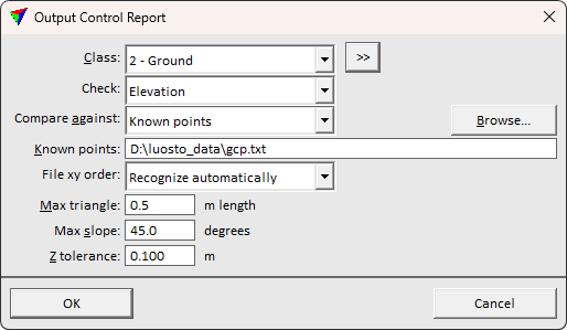
This opens the Output Control Report dialog:
2. Define settings and click OK.
This calculates the elevation differences and opens the Control report window. The content of the report depends on the source file used for the comparison and on the dimension that has been checked. The results and the further usage of a comparison with ground control points is described in detail in Section Systematic elevation or XY(Z) correction.
SETTING |
EFFECT |
|---|---|
Class |
Point class(es) used for the elevation value comparison. |
|
Opens the Select classes dialog which contains the list of active classes in TerraScan. You can select multiple source classes from the list that are then used in the Class field. |
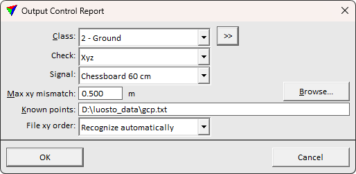
Check |
Dimension to check: •Elevation - the elevation accuracy is checked. •Xyz - the full 3D accuracy is checked. This works only for loaded points and based on signal markers. |
Compare against |
Source file for elevation value comparison: •Known points - text file that contains coordinates of ground control points. •<surface model> - name of a specific surface model active in TerraModeler. This is active only if Check is set to Elevation. |
Signal |
Signal marker definition used for identifying ground control points. The list contains all signal markers that are defined in the Signal markers category of TerraScan Settings, and option None. None option skips automatic signal marker recognition and requires entering the positions in active point cloud manually. This is active only if Check is set to Xyz. |
Max xy mismatch |
Search tolerance for automatic signal marker position extraction. Must exceed the level of mismatch to find the markers in point cloud. |
Known points |
Location and name of the file that stores the coordinates of the ground control points. This is not active if Compare against is set to a surface model. |
File xy order |
The order the coordinate columns appear in the known point text file. |
Max triangle |
Maximum length of a triangle edge. The software creates a triangle from the closest 3 laser points around a ground control point location. If the triangle edge length exceeds the given value, the control point is not used for the report. This is active only if Check is set to Elevation. |
Max slope |
Maximum terrain slope for which an elevation difference is computed. This is active only if Check is set to Elevation. |
Z tolerance |
Normal elevation variation (noise level) of laser points. This value is used only when computing the terrain slope so that small triangles do not exceed the Max slope value. This is active only if Check is set to Elevation. |
