Coordinate transformations / Transformations
Transformations category in Coordinate transformations folder contains a list of coordinate transformations which can be used to transform the position of laser data, trajectories, and other data.
You can Add, Edit, and Delete transformation by using the corresponding buttons in the Settings dialog. The Copy button copies the selected transformation to the clipboard. With the Paste button you can paste a transformation from the clipboard. The Derive button can be used for Deriving a transformation from a set of control point pairs.
Several types of coordinate transformations are supported:
•3D translate & rotate transformation
•Projection change transformation
To define a new transformation:
1. Open the Transformations category in the Coordinate transformations folder.
2. Click Add in the Settings dialog.
This opens the Transformation dialog.
3. Type a Name for the transformation and select a transformation Type. Define the other settings depending on the transformation type.
4. Close the Settings dialog in order to save the modified settings for TerraScan.
You can copy transformations from one Terra application to another. Select the transformation in the Settings dialog and click on the Copy button to copy the definition to the clipboard. Click on the Paste button in the other Terra application to paste the definition.
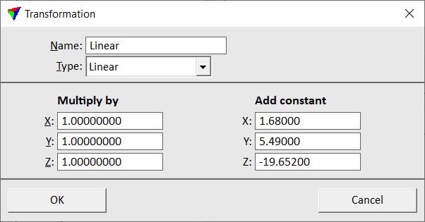
Linear transformation scales and/or translates coordinate values. You can assign a coefficient and a constant offset for each coordinate axis. The target coordinates are computed by multiplying the original coordinates with the given coefficient and by adding a given constant value.
SETTING |
EFFECT |
|---|---|
Multiply by - X |
Coefficient for multiplying the easting coordinate. |
Multiply by - Y |
Coefficient for multiplying the northing coordinate. |
Multiply by - Z |
Coefficient for multiplying the elevation coordinate. |
Add constant - X |
Value to add to the easting coordinate. |
Add constant - Y |
Value to add to the northing coordinate. |
Add constant - Z |
Value to add to the elevation coordinate. |
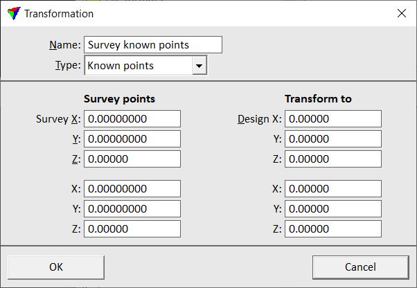
Known points transformation lets you specify the coordinates of two known points in the original coordinate system (survey coordinates) and their respective coordinates in the target system (CAD file coordinates).
SETTING |
EFFECT |
|---|---|
Survey X, Y, Z |
First known point in the original coordinate system. |
X, Y, Z |
Second known point in the original coordinate system. |
Design X, Y, Z |
First known point in the target coordinate system. |
X, Y, Z |
Second known point in the target coordinate system. |
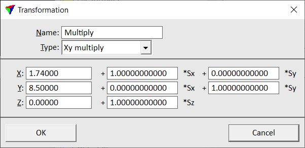
Xy multiply applies a transformation using equations:
NewX = dx + a * Sx + b * Sy
NewY = dy + c * Sx + d * Sy
NewZ = dz + e * Sz
where dx, dy, dz, a, b, c, d, and e are constant parameters of the transformation and Sx, Sy, Sz are the original (survey) coordinates. This is often used as 2D Helmert type of transformation.
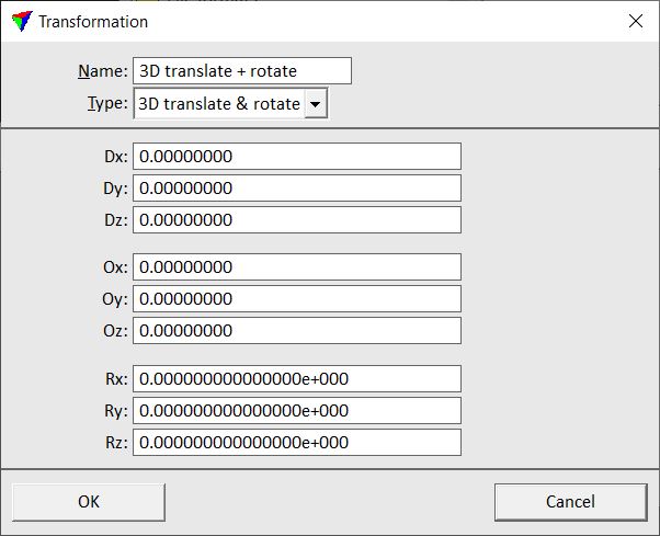
3D translate & rotate transformation
3D translate & rotate applies a three dimensional translation and rotation to coordinates.
SETTING |
EFFECT |
|---|---|
Dx, Dy, Dz |
Values to add to X, Y, Z coordinates. |
Ox, Oy, Oz |
X, Y, Z coordinates of the rotation center point. |
Rx, Ry, Rz |
Rotation angle in radians around X, Y, Z axes. |
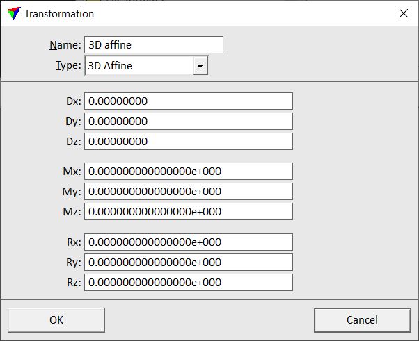
3D Affine applies separate translation, rotation and scaling for each coordinate axis. The transformation is defined by equations:
NewX = dx + (1.0 + mx) * X + rz * Y - ry * Z
NewY = dy + (1.0 + my) * Y - rz * X + rx * Z
NewZ = dz + (1.0 + mz) * Z + ry * X - rx * Y
where dx, dy, dz, mx, my, mz, rz, ry, and rz are constant parameters of the transformation and X, Y, Z are the original coordinates.
SETTING |
EFFECT |
|---|---|
Dx, Dy, Dz |
Values to add to X, Y, Z coordinates (translation). |
Mx, My, Mz |
Factors to scale the data along the X, Y, Z axes. |
Rx, Ry, Rz |
Rotation angle in radians around X, Y, Z axes. |
Projection change transformation
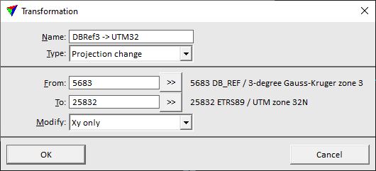
Projection change transforms coordinates from one projection system to another. The software transforms the X, Y, Z coordinates from the source projection system back into WGS84 geocentric X, Y, Z and then computes the transformation into the target projection system.
Projection systems are referenced by their EPSG code (EPSG = European Petroleum Survey Group Geodesy, worldwide unique 4- to 5-digits code numbers for coordinate systems). A list of all available projection systems is opened by clicking the >> button next to the From/To input fields in the dialog. This opens the Browse for Projection System dialog:
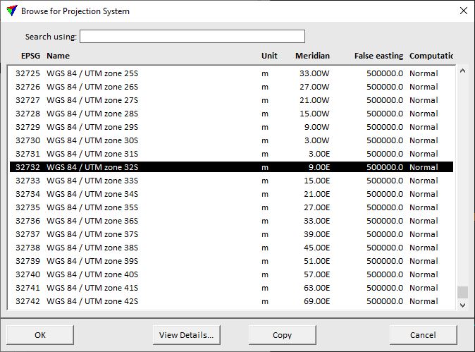
Type parts of the projection system name or code number in the Search using line in order to reduce the list to relevant systems. Select the system you want to use in the list. The View Details button opens an information dialog showing the details of the selected projection system. The Copy button copies the projection system parameters to the clipboard. Click OK in order to use the selected projection system in the Transformations dialog.
If a projection system is not available in the EPSG code list, it can be defined in Coordinate transformations / User projection systems. All systems activated there are also available for a projection change transformation.
SETTING |
EFFECT |
|---|---|
From |
Source projection system. Start typing the name or EPSG code of the system in the text field. The software offers corresponding systems next to the input line. When clicking OK, the system shown next to the input field is used no matter what is typed in the input field. E.g., type "84 UTM 32" in the field. The software shows "32632 WGS 84 / UTM zone 32N" next to the field which is the complete name of the system used for the transformation. Alternatively, use the >> button next to the field to open the complete list of projection systems. |
To |
Target projection system. The input line works in the same way as for the From field. |
Modify |
Coordinate values to modify: •Xyz - modifies all coordinates. •Xy only - no changes to elevation values. |
If you already applied a geoid correction, you should run a reverse geoid correction to the data set before using a projection change transformation. This is essential in cases where the source and the target systems use different ellipsoids or datums. A geoid correction or a reverse geoid correction is only applied automatically if the UK National Grid system is used in the transformation.
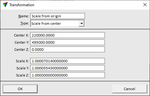
Scale from center applies a scale factor to points relative to a given center point.
SETTING |
EFFECT |
|---|---|
Center X, Y, Z |
XYZ coordinates of the center point. |
Scale X, Y, Z |
Scale factor for the X, Y, Z axes. |
You can also derive transformation parameter values from point pairs. This requires that identical control points (point pairs) are available in source and target coordinate values. The points must be stored in text files. The number of required control point pairs depends on the transformation type.
To derive a transformation, click on the Derive button in the Settings dialog. This opens the Derive transformation from points dialog:
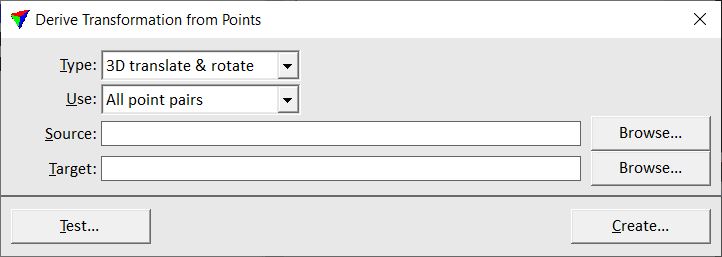
SETTING |
EFFECT |
|---|---|
Type |
Type of the derived transformation: •2D transformation - parameter values for a 2D Helmert transformation are derived. •3D translate & 2D rotate - parameter values for a 3D translation and a 2D rotation transformation are derived. •3D translate & rotate - parameter values for a 3D translation and rotation transformation are derived. •7 parameter affine - parameter values for a 3D affine transformation (7 parameters) are derived. •9 parameter affine - parameter values for a 3D affine transformation (9 parameters) are derived. |
Use |
Points used for deriving the transformation: •All point pairs - uses all control point pairs. •Inside source fence only - points inside a fence in the source coordinate system are used. •Inside target fence only - points inside a fence in the target coordinate system are used. |
Source |
Text file that contains the point pair coordinates in the source system. |
Target |
Text file that contains the point pair coordinates in the target system. |
The transformation derivation can be tested by using the Test button. This computes the parameter values and displays the result in a report window. The report includes residuals which determine how accurate the transformation works.
To create the transformation, click on the Create button. This opens the Transformation dialog that displays the derived parameter values. Type a Name for the transformation and click OK in order to add the transformation to the list in the Settings dialog.