Check Wire Ends
 Check Wire Ends tool can be used to check automatically detected wires in an organized way. The tool opens the Check wire ends dialog which contains user controls for manipulating wires and wire end points. It is intended to be used after automatic wire detection by Find Wires or Find Powerline Wires tool.
The dialog shows a list that contains all wires and their end points. If a line in the list is selected, the software updates the display in a number of CAD file views. The views must be open and defined in the tools settings. The tool can update different view types, such as top, section, and camera views which show either a wire completely or the end point of a wire.
To check wire end points:
1.Select Check Wire Ends tool.
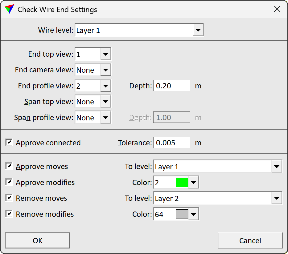
This opens the Check Wire End Settings dialog:
2.Define settings and click OK.
This opens the Check wire ends dialog.
SETTING |
EFFECT |
|---|---|
Wire level |
CAD file level on which the lines for wires have been drawn. All lines on this level are added to the check list. |
End top view |
A top view showing the end of a wire is displayed in the given view. |
End camera view |
A camera view showing the end of a wire in displayed in the given view. This view can be used to display images if a mission, camera, and image list are loaded in TerraPhoto. |
End profile view |
A longitudinal section of the end of a wire is displayed in the given view. |
Span top view |
A rotated top view showing a wire completely in a horizontal section is displayed in the given view. |
Span profile view |
A longitudinal section showing a wire completely is displayed in the given view. |
Approve moves |
If on, the line of an approved wire is moved to the level defined in the To level list. If off, the level of approved wires remains unchanged. |
Approve modifies |
If on, the line color of an approved wire is modified to the given Color. The list contains the active color table of the CAD file. If off, the color of approved wires remains unchanged. |
Remove moves |
If on, the line of a removed wire is moved to the level defined in the To level list. If off, the level of removed wires remains unchanged. |
Remove modifies |
If on, the line color of an removed wire is modified to the given Color. The list contains the active color table of the CAD file. If off, the color of removed wires remains unchanged. |
The Check Wire Ends dialog shows a list that contains all wires and their end points. For each wire, there is a number and two end points. The status of each wire end point is Need to check by default.
Further, the dialog contains buttons that can be used to manipulate wire lines, to change the status of a wire in the list, and to display wire end locations. You can add intermediate vertices to wire lines, move the end points of wire lines, delete points from wire lines, and join wire lines in order to bridge gaps in the automatically detected wires.
If an end point of a wire is moved close to an end point of another wire which is an potential end point for a join, the horizontal and vertical distances between the end points are shown in the dialog.
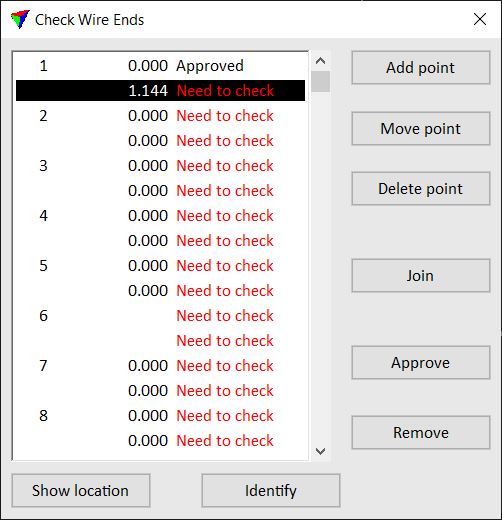
To show the location of a wire end point, select a line in the Check Wire Ends dialog. Click on the Show location button and move the mouse pointer into a view. This highlights the selected wire end point with a cross.
To identify a wire end point, click on the Identify button and place a data click close to a wire end point in a view. This selects the corresponding line in the Check Wire Ends dialog.
After checking a wire end point and possibly improving its location, click on the Approve button. This changes the status of the selected end point to Approved. If both end points of a wire are approved, the wire line is moved to another level and/or the color is changed, if the settings in the Check Wire End Settings dialog are defined accordingly.
If you want to delete a wire, you click on the Remove button. This removes the selected wire from the list and the wire line is moved to another level and/or the color is changed, if the settings in the Check Wire End Settings dialog are defined accordingly. The Remove button does not delete the wire line from the CAD file.
To modify wire lines and their end points, you can use the other buttons of the dialog as described below. You can undo the modification of wires by using the Undo command of the CAD platform.
To add a vertex to a wire:
1.Select the wire in the list.
2.Click on the Add point button and move the mouse pointer into a view, preferably a section view.
This dynamically displays the new vertex and wire line at the mouse pointer location.
3.Define the location of the new vertex by a data click.
You can continue with step 3. The software lets you place only intermediate vertices for the selected wire.
To move an end point of a wire:
1.Select the wire end point in the list.
2.Click on the Move point button and move the mouse pointer into a view.
This dynamically displays the new end point and the wire line at the mouse pointer location.
3.Define the location of the new end point by a data click.
You can continue with step 3. The software lets you move only the selected wire end point.
To delete a point of a wire:
1.Select the wire in the list.
2.Click on the Delete point button and move the mouse pointer into a view.
This dynamically highlights the point on the wire closest to the mouse pointer location.
3.Delete the point by a data click.
You can continue with step 3. The software lets you delete end points and intermediate vertices of the selected wire.
To join wires:
1.Select a wire in the list.
2.Click on the Join button and move the mouse pointer into a view.
This dynamically displays possible connection lines for the selected wire at the mouse pointer location.
3.Move the mouse pointer close to the end point of the wire to which you want to join the selected wire.
4.Confirm a connection line by a data click.
This joins two wire lines. If the status of the effected wires was already Approved, it is set back to Need to check.
Manual changes of the wire lines do not effect the classification of laser points. If you want to refine the classification of laser points on wires, you can run a By centerline classification using the wire lines as centerlines with offset and elevation difference settings of ± a few centimeters.