Check Wire Attachments
Not Lite
 Check Wire Attachments tool validates and adjusts end points of wire strings. At tower locations, the incoming and the outgoing wire strings do not meet exactly because each wire string has been computed using laser points from one tower-to-tower span only. The magnitude of the gap between wire strings gives some indication of how accurately the wires have been detected or placed.
Check Wire Attachments tool produces a list of all tower locations as they are defined by the tower string. For each tower location, the size of the gaps at the wire attachment points are computed in XY and Z. In addition, a shift of the tower positions is computed. A shift unequal to 0 indicates a horizontal shift off from the tower center in direction of the tower string (longitudinal shift). In this case, all incoming wire strings are lower or higher than all outgoing wire strings.
The window displaying the list contains pulldown menus with commands for fixing the gaps automatically or manually.
To validate wire attachment points:
1. Activate a tower string element using the Activate Powerline tool.
2. Select the Check Wire Attachments tool.
This opens the Check Wire Attachments dialog:
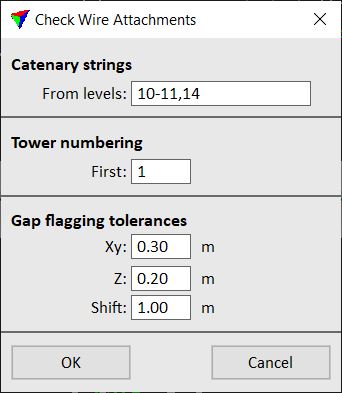
3. Define settings and click OK.
The application searches for wire strings on the given levels and computes gaps between the incoming and the outgoing wires. After the process finished, it opens the Wire Attachments window.
SETTING |
EFFECT |
|---|---|
From levels |
CAD file level(s) from which to search catenaries. Define a range of level numbers by using a minus sign, separate different level numbers by comma. |
First |
Number of the tower at the first vertex of the activated tower string. The numbering is only relevant for the list in the Wire Attachments window. |
Xy |
Xy gap flagging limit. Gaps exceeding this value are displayed with red color in the list. |
Z |
Z gap flagging limit. Gaps exceeding this value are displayed with red color in the list. |
Shift |
Tower shift flagging limit. Shifts exceeding this value are displayed with red color in the list. |
The Wire Attachment window displays the list of wire attachment points for each tower location.
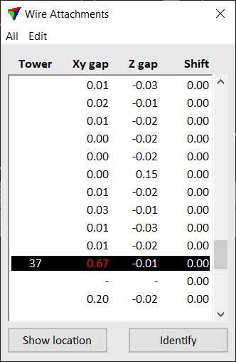
The columns in the window are: tower location number, size of XY gap, size of Z gap, horizontal shift of the tower position. The values are given in 1/100 of the master unit of the CAD file. A - sign for the gaps indicates an open end of a wire string. This is acceptable if a wire starts or ends at a tower. Otherwise, it may indicate very big gaps between incoming and outgoing wire strings.
To show the location of an attachment point, select a line in the window. Click on the Show location button and move the mouse pointer into a view. This highlights the selected location with a cross. Place a data click inside a view in order to center the selected location in the view.
To identify a point, click on the Identify button and place a data click close to a point in a view. This selects the corresponding line in the list of attachment points.
It is recommended to check at least bigger gaps and fix them manually. The commands from the Edit pulldown menu provide tools for moving and connecting wire end points in XY and/or Z. Small gaps can be fixed automatically with commands from the All pulldown menu. In a similar way, shifts of tower positions can be fixed. The manual work of fixing wire attachment points can be supported by laser data loaded in TerraScan. This helps to move wire end points to correct locations.
You can undo actions of the tools by using the Undo command of the CAD platform.
TO |
USE COMMAND |
|---|---|
Shift all tower positions |
|
Adjust all attachment points to the average |
|
Recompute gaps and shifts |
|
View statistics about gaps |
|
Draw attachment markers to the CAD file |
|
Shift a single tower position |
|
Set two connecting wire end points to a given xy location |
|
Adjust a single tower position to the average |
|
Manually enter the location of a wire end point |
Shift all command preforms the same action as the Edit / Shift tower command but for all tower positions of the activated tower string. The command should be used if the shift values are small and tower position are only moved within an acceptable distance.
To shift all towers:
1. Select Shift all command from the All pulldown menu.
This opens the Shift All Towers dialog:
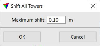
2. Define a Maximum shift distance and click OK.
This moves the vertices of the tower string representing the tower position and the wire attachment points for all positions for which a shift correction applies. If the computed shift of a tower position exceeds the Maximum shift value, the additional shift remains. The gap values in the Wire Attachments window are updated automatically.
An information dialog shows the number of shifted tower positions.
Adjust all command performs the same action as the Edit / Adjust attachment command but for all attachment points. The command should be used if the gap values are small and the attachment points are only moved within an acceptable distance.
To adjust all attachment points:
1. Select Adjust all command from the All pulldown menu.
This opens the Adjust All Attachments dialog:
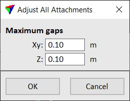
2. Define maximum values for Xy and Z gaps to be corrected and click OK.
This adjusts all attachment points for which both, the horizontal gap and the vertical gap are within the defined limits. The end point of the incoming wire string and the start point of the outgoing wire string are adjusted to the average XYZ position between the two. The gap values in the Wire Attachments window are updated automatically.
Update list command recomputes the gap and shift values for wire strings and updates the list. The command should be used if
•a wire string has been deleted or added.
•an action has been undone using the Undo command of the CAD platform.
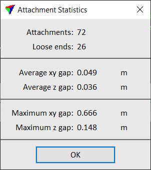
Statistics command displays statistical information about wire attachment points. This includes:
•Attachments - number of wire attachment points.
•Loose ends - number of wire end points that do not have an attachment to another wire string. This is the case at the start and end of a tower string because there are no incoming/outgoing wire. If there are more loose ends, it indicates missing wire strings due to problems in wire detection, or too big gaps between incoming and outgoing wire strings at an attachment point.
•Average xy gap - average size of horizontal gaps at attachment points.
•Average z gap - average size of elevation gaps at attachment points.
•Maximum xy gap - size of the largest horizontal gap.
•Maximum z gap - size of the largest elevation gap.
The values may be helpful to decide whether manual work for fixing gaps is required or not. In the end, when all gaps are closed, all values should be 0.
Draw Markers command draws specified marker to catenary attachment points.
To draw all attachment markers:
1. Select Draw Markers command from the All pulldown menu.
This opens the Draw markers dialog:
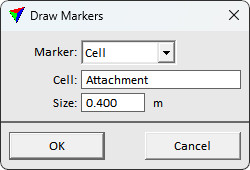
2. Define settings and click OK.
This draws specified type of marker to all catenary attachments. An information dialog shows the number of drawn markers.
SETTING |
EFFECT |
|---|---|
Marker |
Marker type: •Cell - Bentley cell element. •Character - text characters on horizontal plane. •Circle - circle on horizontal plane. |
Cell |
Name of the cell definition. Visible only if Marker is set to Cell. |
Character |
Characters as text input. Visible only if Marker is set to Character. |
Size |
Size of the markers drawn. |
Radius |
Circle marker radius. Visible only if Marker is set to Circle. |
Shift tower command shifts a tower position along tower string direction (longitudinal shift). In can be used for places where all incoming wires are higher/lower than corresponding outgoing wires. Shifting the tower position moves all attachment points towards the previous/next tower and thus, lowers/raises the attachment points of incoming /outgoing wires.
To shift a single tower position:
1. Select Shift tower command from the Edit pulldown menu.
2. Move the mouse pointer inside a view.
The tower closest to the mouse pointer is highlighted by a red or green square. The square shows the target location of the tower position shift. The color indicates whether the shift can be performed (green) or not (red).
3. Confirm the new position with a data click.
This moves the vertex of the tower string representing the tower position and the wire attachment points. The gap values in the Wire Attachments window are updated automatically.
Set attachment xy command moves a single attachment point to a given XY location. At the same time, it moves the end/start points of the incoming and outgoing wire strings to the same XY location. The elevation of the wire end/start points stays unaffected.
To set xy location of an attachment point:
1. Select Set attachment xy command from the Edit pulldown menu.
2. Move the mouse pointer inside a top view.
The attachment point closest to the mouse pointer is highlighted by a green square. The square shows the target location of the attachment point.
3. Select the attachment point with a data click.
4. Define the XY location with a data click.
This moves the wire end points to the XY position of the data click. It does not modify the wire constants or the elevation of the wire end points. The gap values in the Wire Attachments window are updated automatically.
You can continue with step 3.
Adjust attachment command adjust a single attachment point to the average of the incoming and the outgoing wires’ end/start points. It effects both, the XY and Z position of the attachment point.
To adjust a single attachment:
1. Select Adjust attachment command from the Edit pulldown menu.
2. Move the mouse pointer inside a top or section view.
The attachment point closest to the mouse pointer is highlighted by a green square. The square shows the target location of the attachment point. The color indicates whether the adjustment can be performed (green) or not (red).
3. Select the attachment point with a data click.
This moves the end point of the incoming wire string and the start point of the outgoing wire string to the new location. The gap values in the Wire Attachments window are updated automatically.
You can continue with step 3.
Move wire end command lets you move a wire start/end point to a new location. The tool should be used if one of the wires matches laser points better than the other one. You can either move the XY position, the Z position, or both at the same time. CAD platform snapping functionality can be used to snap start/end points to each other.
To move a wire end or start point:
1. Choose Move wire end command from the Edit pulldown menu.
This opens the Move Wire End dialog:
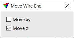
2. Select the position(s) you want to modify.
3. Move the mouse pointer inside a top or section view.
The wire start/end point closest to the mouse pointer is highlighted by a green square.
4. Select the start or end point with a data click.
5. Define the new location of the start/end point with another data click.
This recomputes and redraws the wire string. The gap values in the Wire Attachments window are updated automatically.
You can continue with step 4.