

TerraModeler User Guide
Display Slopes
 Display Slopes tool draws a grid of slope arrows. Each slope arrow shows the direction of water flow at this location. The arrow length indicates the steepness of the surface at this location. The tool can also create labels along the arrows which show the gradient of the slope.
To display slope arrows:
1. Select the Display Slopes tool.
The Display Slopes dialog opens:
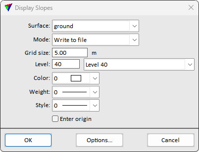
2. Define settings.
3. (Optional) Click on the Options button in order to open the Slope Settings dialog and define settings for slope arrow symbology.
4. Click OK to the Display slopes dialog.
5. If Enter origin is switched on, enter the origin point of the grid with a data click.
This draws slope arrows for the selected surface model on the given level.
Setting |
Effect |
|---|---|
Surface |
Name of the effected surface model. |
Mode |
Display mode for slope arrows: •Write to file - elements are written and stored in the CAD file. |
Grid size |
Distance between slope arrow locations. |
Level |
Number of the level in the CAD file on which slope arrows are drawn. |
Color |
Color of the arrows. Uses the CAD file color table. |
Weight |
Line weight of the arrows. Uses CAD file line weights. |
Style |
Line style of the arrows. Uses CAD file line styles. |
Enter origin |
If on, you can enter the origin point of the grid with another data point. If the point is inside the surface area, an elevation text is drawn at this location. |
Options |
Opens the Slope Settings dialog. See Slope settings for more information. |
The Slope Settings dialog defines the symbology and label display options for slope arrows created by the Display Slopes tool.
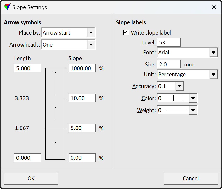
Setting |
Effect |
|---|---|
Place by |
Placement point (= point of elevation measurement) of a slope arrow: Arrow start or Arrow center. |
Arrowheads |
Number of arrowheads of a slope arrow: •One - all arrows have one arrowhead. •One to three - number of arrowheads depends on the slope. |
Length |
Two fields specifying the maximum and the minimum length of a slope arrow. |
Slope |
Slope values at which the arrow length is equal to: - maximum length - two thirds of maximum length - one third of maximum length - minimum length |
Write slope label |
If on, a text label showing the slope gradient is placed along a slope arrow. |
Level |
Level number in the CAD file on which the label is placed. |
Font |
Font type of slope arrow labels. Uses font types available in the CAD platform. |
Size |
Text size of slope arrow labels. Given in millimeters on paper. |
Unit |
Measurement unit of label value Percentage or Degree. |
Accuracy |
Number of decimals in the slope arrow label. |
Color |
Color of slope arrow labels. Uses the active color table of the CAD file. |
Weight |
Line weight of slope arrow labels. Uses the CAD file line weights. |