Fit Linear Element
 Fit Linear Element tool improves the horizontal accuracy of manually placed linear elements by fitting the xy location of vertices to laser points. The resulting linear element follows laser points more closely.
Valid CAD element types for this tool include lines, line strings, shapes, and complex shapes. You can fit several selected elements in a single process.
To fit linear elements:
1. (Optional) Select the element(s) that you want to fit.
2. Select the Fit Linear Element tool.
This opens the Fit Linear Element dialog:
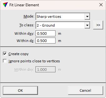
3. Define settings and click OK.
If elements have been selected, they are fitted to the laser points.
4. Identify the element to fit with a data click.
This highlights the given element.
5. Accept the highlighted element with another data click.
This fits the selected element to follow laser points more accurately. You can continue to step 4.
SETTING |
EFFECT |
|---|---|
Mode |
Defines whether vertices are added to the fitted element or not: •Sharp vertices - no additional vertices are added. Suitable for fitting elements with straight line segments between sharp turns (for example overhead wires). •Smooth curvature - additional vertices may be added. Suitable for fitting an element which has smooth curvature only (for example paint line on a road). |
To class |
Point class to fit to. Contains the list of active classes in TerraScan. |
|
Opens the Select classes dialog which contains the list of active classes in TerraScan. You can select multiple source classes from the list that are then used in the To class field. |
Within dxy |
Maximum horizontal offset of laser points to be used in the fitting process. |
Within dz |
Maximum vertical offset of laser points to be used in the fitting process. Enter a large value such as 999.000 if you want to use all laser points regardless of their elevation. |
Create copy |
If on, a copy of the original element is created and fitted. The new element is placed on the active level using active symbology settings of the CAD file. If off, the original element is fitted. |
Ignore points close to vertices |
If on, the fitting process ignores points within the distance to element vertices given in the Within dxy field. This is active only if Mode is set to Sharp vertices. |
Add vertices to long segments |
If on, the fitting process adds intermediate vertices along long segments. The distance between consecutive vertices is given in the Step field. This is active only if Mode is set to Smooth curvature. |
Smoothen curvature |
If on, the curvature of the fitted element is smoothed by balancing angular direction changes between consecutive vertices. This is active only if Mode is set to Smooth curvature. |
