Draw Vertical Section
 Draw Vertical Section tool creates a 3D section view from a location defined by a center line of the section and its depth.
A vertical section view is simply a rotated CAD file view which displays all visible CAD file elements and laser points inside the given slice of space. This makes it well-suited for viewing laser points and for placing 3D vector elements.
To create a vertical section view:
1. Select the Draw Vertical Section tool.
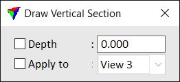
The Draw Vertical Section dialog opens:
2. Define the start or left point of the section center line with a data click in a top view.
3. Define the end or right point of the section center line with a data click in a top view.
4. Define the section view depth with a data click in a top view or by typing a value in the Depth field of the Draw Vertical Section dialog.
5. If Apply to is not switched on in the Draw Vertical Section dialog, select the view for displaying the section with a data click inside this view.
The selected view is rotated to show the vertical section. The application automatically computes the required elevation range so that all laser points inside the given section space are displayed.
SETTING |
EFFECT |
|---|---|
Depth |
Display depth of a section on both sides of the center line. If on, the depth is fixed to the given value. |
Apply to |
If on, the section is automatically displayed in the selected view. |