Cut overlap
Not Lite
Cut overlap command removes laser points from locations where laser data from multiple lines overlap. The points of overlapping areas can be classified to a specific class or classes, or they can be deleted from the data set. In LAS 1.4 files, the overlap bit can be set instead of classifying or deleting points.
There are several methods for cutting off overlap. If you want to apply several methods to a data set, run the one method after another in separate processing steps in order to avoid incorrect results.
General procedure to cut overlap:
1. Select Cut overlap command from the Line pulldown menu.
This opens the Cut Overlap Points dialog:
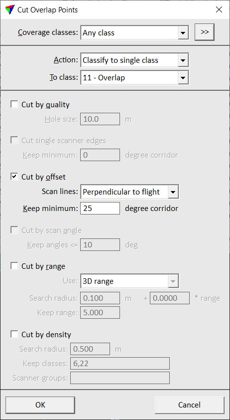
2. Define settings and click OK.
This classifies/removes points from overlapping areas.
SETTING |
EFFECT |
|---|---|
Coverage classes |
List of point classes to consider when determining if a line covers an area. The tool modifies points in these classes only. |
Select |
Opens the Select classes dialog which contains the list of active classes in TerraScan. You can select multiple source classes from the list that are then used in the Coverage classes field. |
Action |
Action to perform on points in overlapping areas: •Add constant to class - add a given value to the class number. •Classify to single class - classify points into one target class. •Delete - remove points from the data set. •Set overlap bit - sets the overlap bit for points in LAS 1.4 files. |
Add |
Value to add to class numbers if Action is set to Add constant to class. |
To class |
Target class if Action is set to Classify to single class. |
Cut by quality
Cut by quality method removes lower quality laser points from locations where there is laser data from a higher quality line. The method is suited if:
•there is laser data from two different flying altitudes. Data of a lower flight line is normally more accurate than data of a higher line.
•the hardware was not working at the best level for some lines.
•the GPS trajectory is weak for some lines.
•there is laser data from single crossing lines while the majority of lines follows another direction.
You can define the quality of lines as an attribute of imported trajectories. See Manage Trajectories tool and Edit information command from the Trajectory window for more information. If you do not have imported trajectories, you can assign quality values to different line number sequences in the Default flightline qualities category of TerraScan Settings.
Before cut |
After cut by quality |
Point color: red points are from a lower quality line, blue points from a higher quality line |
|
SETTING |
EFFECT |
|---|---|
Cut by quality |
If on, cut by quality method is applied. |
Hole size |
Approximate maximum diameter of hole. If a larger area is not covered by points of a higher quality line, points from the lower quality line are kept. |
Cut single scanner edges
Cut single scanner edges method is designed for removing overlap in data sets collect by airborne dual-scanner systems. It removes edges of lines that are captured by one scanner only.
SETTING |
EFFECT |
|---|---|
Cut single scanner edges |
If on, cut single scanner edges method is applied. |
Keep minimum |
Minimum central part of a line and scanner to keep. A value of 20 would keep a +10.. -10 degree corridor of each line and scanner. |
Cut by offset
Cut by offset method removes laser points from the edges of lines if the same location is covered more vertically from another line. This method serves two purposes:
•Removing edges of lines produces a more uniform point density and point pattern.
•The magnitude of error sources grows with increasing scan angle. Removing edges of lines removes less accurate points and keeps the more accurate central part of a line.
The method is suited for cutting off overlap between parallel lines in an airborne data set. It requires trajectory information and matching line numbers of points and trajectories. See Deduce using time command for more information about matching line numbers of points and trajectories easily. If time stamps are not available for laser points, the application uses a perpendicular projection from a laser point to the trajectory.
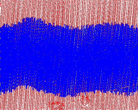
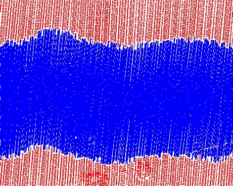
Before cut |
After cut by offset |
Point color: different colors represent points of different lines |
|

SETTING |
EFFECT |
|---|---|
Cut by offset |
If on, cut by offset method is applied. |
Scan lines |
Scan line pattern of the data set: •Perpendicular to flight - parallel or zigzag scan lines. •Elliptical - elliptical scan lines. |
Keep minimum |
Minimum central part of a line to keep. A value of 20 would keep a +10.. -10 degree corridor of each line. |
Cut by scan angle
Cut by scan angle method removes points with a scan angle that is larger than a given value. It removes the edges of lines similar to the Cut by offset method but does not rely on trajectory information.
SETTING |
EFFECT |
|---|---|
Cut by scan angle |
If on, cut by scan angle is applied. |
Keep angles <= |
Points with scan anlges smaller or equal to the given value are kept. |
Cut by range
Cut by range method removes laser points from the edges of a line if the same location is covered by points from a shorter measurement distance. This method is designed for laser data from mobile ground-based systems.
The software searches for points inside a sphere and cuts off points resulting from long measurements if points from a shorter range within the search radius are present. The range can be defined as 3D range or offset range. In addition, the method can favor points from first- or last-in-time passes. This simplifies the removal of data from duplicated passes, e.g. when a mobile system collected data in a city driving streets several times.
The method requires trajectory information and matching line numbers of points and trajectories. See Deduce using time command for more information about matching line numbers of points and trajectories easily.
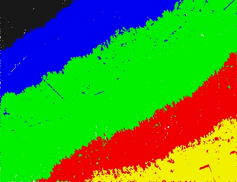
Before cut |
After cut by 3D range |
After cut by offset range |
Point color: different colors represent points of different lines |
||
SETTING |
EFFECT |
|---|---|
Cut by range |
If on, cut by range method is applied. |
Use |
Method to use for cut by range: 3D range, 3D range - favor first, 3D range - favor last, Offset range, Offset range - favor first or Offset range - favor last. |
Search radius |
Radius of a sphere within which the software searches for closer range points from another line. The radius can be automatically increased as a factor of the range. By increasing the radius at longer ranges, the method is more eager to keep points from more distant lines. |
Keep range |
Range from scanner within which all points are kept. |
Cut by density
Cut by density method is developed for removing overlap in merged point clouds from different sensors. The merged point cloud is a result of several point clouds with significantly different point densities. Examples are point clouds from mobile and airborne laser scanners, or photogrammetric airborne and terrestrial laser point clouds. Some areas may be covered by both sensors but other areas just by one sensor. In overlap areas, the method keeps the data from the sensor with the higher point density and removes more sparse data from the other sensor.
The cut overlap method requires scanner numbers assigned to the points. The data from different sensors is identified by a unique scanner number.
SETTING |
EFFECT |
|---|---|
Cut by density |
If on, cut by density method is applied. |
Search radius |
Determines the area in which the local density is computed. |
Keep classes |
Point class(es) from which all points are kept even if the density is lower than in data from another sensor. Examples: roofs from airborne laser data, hard surface areas from mobile laser data. |
Scanner groups |
If a range of scanner numbers is given, the corresponding sensors are treated as a group. For example, if there is data from two mobile laser scanners with numbers 1 and 2, and the scanners are calibrated, use 1-2 in order to define a group for these 2 scanners. Separate different groups by semicolon, for example 1-2;3-4. If the field is empty, each sensor is treated individually. |