Adjust laser angles
Not Lite
Adjust laser angles command applies a positional correction to laser points. The command is normally used to fix misalignment of lines in the laser data. The software computes an XYZ correction for a point as true angular rotation of the vector from the scanner to the point. The user can then decide, whether the full correction is applied or only a partial horizontal/vertical correction along the XY or Z axis.
Adjust laser angles requires trajectory information in order to determine the scanner position of each laser point. Therefore, trajectories must be imported into TerraScan and the line numbers of laser points must match the numbers of trajectories. See Deduce using time command for more information about matching line numbers of points and trajectories easily.
Time stamps for laser points are not mandatory. If time stamps are present, the application can derive the laser scanner position for each laser point more accurately. If time stamps are missing, the application uses a perpendicular projection from a laser point to the trajectory in order to determine the scanner position.
To adjust laser angles:
1. Select Adjust laser angles command from the Line pulldown menu.
This opens the Adjust Laser Angles dialog:
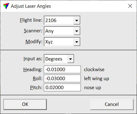
2. Define settings and click OK.
The application derives the laser scanner position for each point and applies a positional correction according to the settings.
SETTING |
EFFECT |
|---|---|
Flight line |
Line to which the correction is applied. Select Any in order to apply the correction to all loaded points. |
Scanner |
Scanner to which the correction is applied. This can be used for data from multi-scanner systems. Select Any in order to apply the correction to all loaded points. |
Modify |
Coordinate axis to modify: •Xyz - applies a full 3D correction. •Xy - applies a horizontal shift relative to trajectory and movement direction. •Z - applies a vertical shift relative to trajectory and movement direction. |
Input as |
Unit of misalignment correction values: •Degrees - angles given in decimal degrees. •Radians - angles given in radians. •Ratio - angles given as a ratio over a value corresponding to a full circle. |
Heading |
Heading angle correction, positive values increase in clockwise direction. |
Roll |
Roll angle correction, positive values increase in left wing up direction. |
Pitch |
Pitch angle correction, positive values increase in nose up direction. |