Horizontal / Create geometry
Create geometry command generates a preliminary horizontal geometry.
The preliminary geometry is a combination of the geometry components arcs and lines. You can include transition curves using the Tools / Change curved set mode command. Almost all commands for modifying a geometry work on curved component sets with and without transition curves. The transition curve type that is currently implemented is clothoid.
To generate a preliminary horizontal geometry:
1. Select the filtered survey vector element using CAD platform Selection tool.
2. Select Create geometry command from the Horizontal pulldown menu.
This opens the Create horizontal geometry components dialog:
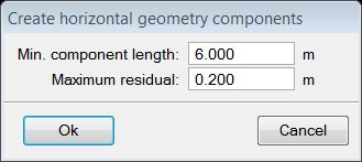
3. Define settings and click OK.
This starts the automatic process for generating a preliminary geometry.
SETTING |
EFFECT |
|---|---|
Min. component length |
The application attempts to generate a geometry that has components longer than this value. Usually, the components are much longer and this value only comes into effect in extreme cases. Typically, the value should be at maximum 0.5 * the known minimum component length. Larger values can cause the application to miss components and producing poor-quality geometry. |
Maximum residual |
Determines the goal for the level of agreement between the generated geometry and the vertices of the line string. In other words, the application adds components or continues to try to converge the components until this level of agreement is reached. Typically, the value is comparable to the noise level of the data. In test cases, average residuals were less than 0.1 m, maximum residuals about 0.2 m. A value that is too small can cause the preliminary geometry generation to be slow or fail. |
Road fit: results
The Road fit: results dialog is opened after the preliminary horizontal geometry components have been created:
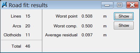
The dialog shows a general overview of the geometry. It lists the total number of the components in the geometry as well as the number of different types of components ( line, circular arc, clothoid ). The dialog also reports the differences between the geometry and the filtered line string by giving
•the largest distance from the geometry to a point in the line string (Worst point)
•the largest average residual that a single component has (Worst comp.)
•the average residual (Average residual).
The two Show buttons can be used to pan the view to the component with the worst point-wise residual or the worst average residual. The values of the dialog are automatically updated as the geometry is modified. Checking these values is a fast way to detect problems in the geometry.
Current geometry
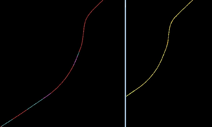
The horizontal geometry is stored in the CAD file (on level 23 as the default). The different components of the geometry are color-coded, the default colors for lines is light blue, for circular arcs red and for clothoids purple. The colors for components and the level for the geometry can be defined in TerraScan Settings, see also User settings.
An example of a segment of a road with different types of components can be seen in the illustration below.
The elements written in the CAD file are standard CAD elements grouped together into a cell. For the component fitting application, they are mostly the visual representation of the geometry but include information about the components. This means that the components can be regenerated from the elements of the CAD file.
The geometry components in the CAD file are automatically updated if they are modified with the commands of the component fitting application. Modifications of the elements drawn for components in the CAD file are not recommended but they do not effect the components that are stored internally by the component fitting application. If components are redrawn by the component fitting application, they are always redrawn at their position that is stored internally.
Component fitting main window
After the preliminary geometry generation, the geometry components are listed in the Component fitting main window. The only way to select a component for modification is by selecting it in the list of this window.
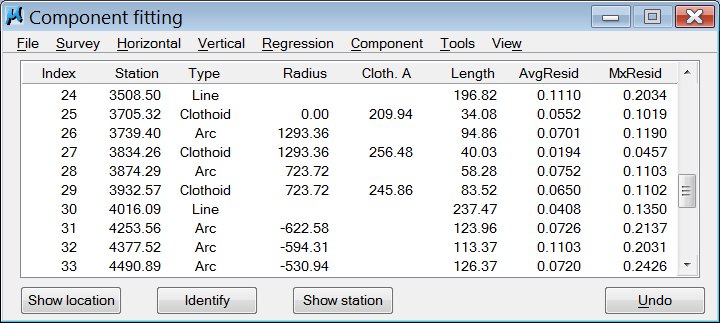
To show the location of a geometry component, select a line in the Component fitting window. Click on the Show location button and move the mouse pointer into a view. This highlights the selected component. Place a data click inside the view in order to center the component in the view. If horizontal and vertical geometries are present, you can select in the Show location dialog which one to use for panning a view.
To identify a geometry component, click on the Identify button and place a data click close to a component in a view. This selects the corresponding line in the Component fitting window. Only components of the currently active geometry (vertical or horizontal) can be selected.
To display the station and the signed residual between the geometry and the line string for the currently active (horizontal or vertical) geometry, click on the Show station button and move the mouse pointer into a view. Positive residuals of a horizontal geometry mean that the geometry component is on the left of the line string. Positive residuals of a vertical geometry mean that the geometry component is below the line string.
Use the Undo button in order to undo a modification. You can undo up to 20 modifications.
VALUE |
DESCRIPTION |
|---|---|
Index |
Index of the component. Numeration starts at 0. |
Station |
Starting station of the road component. The value indicates the distance from the first vertex of the filtered line string to the first vertex of the component measured along the filtered line string. |
Type |
Type of the component: Line, Arc, or Clothoid. Arc means a circular arc. |
Radius |
Starting radius of curvature of the component. The sign of the radius indicates the direction of the turn (counter-clockwise or clockwise ). In the case of circular arcs, the starting radius is always finite. However, 0.00 is displayed for circular arcs if the value for the radius is larger than the number of digits available in the field. |
Cloth. A |
Value of the clothoid parameter. |
Length |
Length of the component. It is possible to end up with 0.0 length components when components are modified. You should try to join the zero-length components with other components. |
AvgResid |
Average distance between the component and vertices of the line string that are closer to this component than any other. Value 0.00 means that none of the vertices are closer to this component than any other component. You should try join such components with other components. |
MxResid |
Maximum distance from the component to a vertex of the line string that is closer to this component than any other. Value 0.00 means that none of the points are closer to this component than any other component. |