Detect Wires
Not Lite
 Detect Wires tool is used to vectorize wires and classify points on wires of a powerline. It draws line string elements in the CAD file for all detected wires. The tool runs on points loaded in TerraScan.
The tool searches points along a catenary curve. Catenary curves are mathematical descriptions of wires that are connected at their end points but hanging free between these end points. The process involves least squares fitting for both, the xy line equation and the elevation curve equation of the catenary.
The most important parameter controlling wire detection is Max gap which defines the maximum gap between consecutive laser points on a wire. It is not advisable to run the detection on the whole data set with a large maximum gap value because the chance of false detections increases. It is recommended to run the detection first with a relatively small maximum gap value which does not necessarily detect all wires. For locations with fewer points on the wires, the detection should be done for single segments with a smaller value.
The Detect Wires tool requires a tower string element that is has been created, for example, with the Place Tower String tool. The tower string must be activated. The line string elements for detected wires are drawn on the active level using the active symbology settings of the CAD file.
To detect wires:
1. Activate a tower string element using the Activate Powerline tool.
2. Select the Detect Wires tool.
This opens the Detect Wires dialog:
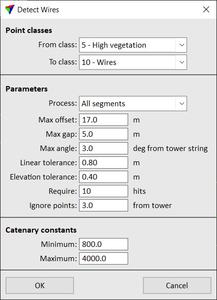
3. Define settings and click OK.
If Process is set to All segments, the application starts to detect wires.
4. If Process is set to Single segment, move the mouse pointer inside a top view. The segment closest to the mouse pointer is highlighted.
5. Select the segment to process with a data click.
This starts the detection of wires for the selected segment.
A progress window shows the progress of the process. Depending on the data set, the process may take some time, especially if there is vegetation close to the wires.
SETTING |
EFFECT |
|---|---|
From class |
Point class from which wires are detected. |
To class |
Target class into which points on wires are classified. |
Process |
Determines where wires are detected: •All segments - for all segments for which data is loaded in TerraScan. •Single segment - only for the selected tower-to-tower segment. |
Max offset |
Maximum distance from the tower string element to the left/right side to detect wires. Defines the corridor in which the software searches for wires. |
Max gap |
Maximum allowed gap between consecutive points on a wire. |
Max angle |
Maximum allowed angle between a wire and the tower string element. |
Linear tolerance |
Tolerance for XY line fitting and classification of points on a wire. |
Elevation tolerance |
Tolerance for elevation curve fitting and classification of points on a wire. |
Require |
Minimum amount of laser points on a single wire required for detection. Values can range from 3 to 999. |
Ignore points |
Distance from tower within which points are ignored for wire detection. Points close to the tower can be from tower structures and should be ignored when determining the mathematical shape of the wire. |
Minimum |
Minimum catenary constant to accept a wire. |
Maximum |
Maximum catenary constant to accept a wire. |
The vectorization of the wires can be undone by using the Undo command of the CAD platform. The classification of the wires can be undone by using the Undo command of TerraScan.