Read / Building models
Read / Building models command reads text files that have been created in an automatic building vectorization process. It is used to draw the buildings as 3D vector models into the CAD file. See Vectorize buildings macro action for more information about the creation of building text files.
The complete building models are drawn as cell elementsBentley CAD or symbolsSpatix into the CAD file. If only selected components of a model are drawn, the software creates single polygon elements. The settings in Building vectorization / Levels and Building vectorization / Model categories of TerraScan Settings determine level, color, and layout definition of the models.
After drawing the building models into the CAD file, they can be checked and modified using dedicated tools of TerraScan. They are described in detail in Chapter 3D Building Models.
To read building models into the CAD file:
1. Select Read / Building models command from the Tools pulldown menu.
This opens the Read building models dialog, a standard dialog for opening files.
2. Select building text files and click Open.
This opens the Read Building Models dialog:
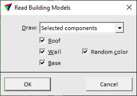
3. Select settings and click OK.
This reads the text files and draws the building models into the CAD file.
SETTING |
EFFECT |
|---|---|
Draw |
Determines what components of a building model are drawn: •Complete model - all parts are drawn which includes polygons for roof planes, walls, and a base polygon. •Selected components - only selected parts of a model are drawn. |
Roof |
If on, polygons for roof planes are drawn. |
Wall |
If on, polygons for walls are drawn. |
Random color |
If on, walls are drawn by using colors chosen randomly from the active color table of the CAD file. If off, the color defined in Building vectorization / Model category of TerraScan Settings is used for all walls. This is only active if Wall is switched on. |
Base |
If on, the base polygon is drawn. |
You can undo the action by using the Undo command of the CAD platform.