Fit to reference
Fit to reference command applies a systematic correction to a data set. The correction may include translation in XYZ direction and rotation around XYZ axes. Alternatively, a rubbersheet correction (correction that changes over time) can be computed to fit data in elevation.
The correction is computed based on reference points loaded into TerraScan. See Read reference points command for more information. The correction is applied to the active points loaded in TerraScan.
The command is primarily developed for change detection of volumes in mines based on photogrammetric point clouds. The detection and computation of volume changes requires that the point clouds of, for example, two days match where there was no change. Thus, the command can be used to fit two photogrammetric point clouds in preparation of volume computation. While a systematic shift can be done with all (ground) points of the point cloud, it is recommended to exclude areas that have changed for the rubbersheet fit. This can be done by drawing polygons around such areas and classify points inside the polygons into a separate class.
To fit points to reference points:
1. Load points and reference points into TerraScan.
2. Select Fit to reference command from the Tools pulldown menu.
This opens the Fit to Reference dialog:
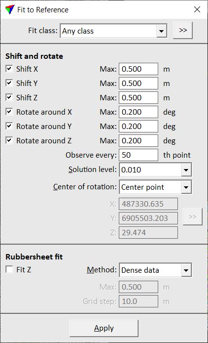
3. Define settings and click OK.
This fits the active points to the reference points.
SETTING |
EFFECT |
|---|---|
Fit class |
Class(es) used for computing the fit. |
|
Opens the Select classes dialog which contains the list of active classes in TerraScan. You can select multiple source classes from the list that are then used in the Fit class field. |
Shift X |
If on, a translation in X direction is computed and applied up to the given Maximum value. |
Shift Y |
If on, a translation in Y direction is computed and applied up to the given Maximum value. |
Shift Z |
If on, a translation in Z direction is computed and applied up to the given Maximum value. |
Rotate around X |
If on, a rotation around the X axis is computed and applied up to the given Maximum value. |
Rotate around Y |
If on, a rotation around the Y axis is computed and applied up to the given Maximum value. |
Rotate around Z |
If on, a rotation around the Z axis is computed and applied up to the given Maximum value. |
Observe every |
Determines how many points are used for computing the translation and rotation correction. |
Solution level |
Level of accuracy for the correction values. The selection list provides some accuracy levels depending on the CAD file master and secondary units. |
Center of rotation |
Defines the center point for rotating the point cloud: •Center point - center point of the active point cloud. •User point - user-defined point. |
X | Y | Z |
XYZ coordinate values of the center of rotation. Define the point by typing values in the text fields or by using the >> button next to the coordinate fields. This is only active if Center of rotation is set to User point. |
|
Lets you define the point of rotation with a data click inside a CAD file view. You may use the snapping functionality of the CAD platform to define the point exactly based on an element drawn in the CAD file. This is only active if Center of rotation is set to User point. |
Fit Z |
If on, a rubbersheet correction in Z direction is computed. |
Method |
Method of computing rubbersheet correction values: •Dense data - grid-based suited for dense point clouds. •Sparse data - based on point-to-point spacing suited for sparse point clouds. |
Max |
Maximum rubbersheet correction value applied to the active point cloud. |
Grid step |
Defines the grid step size for computing correction values. This is only active if Method is set to Dense data. |
Spacing |
Defines the maximum space between correction values. This is only active it Method is set to Sparse data. |
