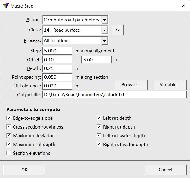
Compute road parameters
Not Lite
Compute road parameters action extracts information from cross sections at regular spacing along a road. The extraction requires a high density of points on the road surface. Therefore, the action is only suited for MLS data sets. It requires the classification of points on the road surface using the Hard surface routine. Additionally, points close to the surface points should be classified using the By distance routine, for example points within an elevation range of ±1 cm.
The section parameter extraction relies on an alignment element, such as a line string representing the centerline of a road. An Offset parameter in the action settings defines on which side of the alignment (left or right) the cross sections are extracted. The left or right side is defined relatively to the digitization direction of the alignment element. To get cross section parameters for both sides, you need to add the Compute section parameters action two times to a macro.
The following list contains the cross section parameters that can be extracted:
•Edge to edge slope - slope from the middle of the two leftmost points to the middle of the two rightmost points.
•Cross section roughness - average distance of points to a line connecting the left- and rightmost points.
•Maximum deviation - maximum distance from a point to a line connecting the left- and rightmost points. The value is positive if the point is above the line and negative if the point is below the line.
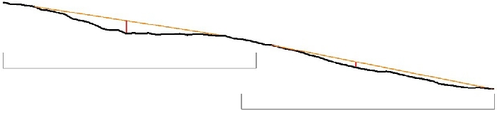
•Maximum rut depth - maximum elevation distance from a point to a line connecting two other points in the section. The elevation distance is always measured downward from the line to the point.
•Left rut depth - the left rut is searched in an interval from the left edge to the first point on the right side of the cross section center. The left rut depth is the Maximum rut depth within this interval (see illustration below).
•Right rut depth - the right rut is searched in an interval from the right edge to the first point on the left side of the cross section center. The right rut depth is the Maximum rut depth within this interval (see illustration below).
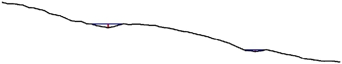
•Left rut water depth - searched in the same interval as the Left rut depth. The rut water depth is the maximum elevation difference from a point to a water surface in the left rut (see illustration below).
•Right rut water depth - searched in the same interval as the Right rut depth. The rut water depth is the maximum elevation difference from a point to a water surface in the right rut (see illustration below).
•Section elevations - elevation distances between points to the fitted section line. The line is fitted to all points of a cross section within a given tolerance. The elevation distance is measured at given regular steps along the cross section, for example every 5 cm.
The process writes the section parameters into text files, one for each block binary file of a TerraScan project. Depending on the selection of parameters for extraction, the text files contain more or less columns with the section parameter values.
The text files can be read into the CAD file by using the Read / Section parameters command in order to visualize the cross section parameters.
You must select the alignment element before starting a macro with the Compute road parameters action.
SETTING |
EFFECT |
|---|---|
Class |
Source class(es) that are included in the section parameter extraction. |
|
Opens the Select classes dialog which contains the list of active classes in TerraScan. You can select multiple source classes from the list that are then used in the From class field. |
Process |
Area to process and include in the output file: •All locations - area covered by the active block binary file and possibly neighbouring areas, if neighbour points are loaded for the macro execution. •Inside active block - area covered by the active block binary file. |
Step |
Distance between consecutive cross sections. Measured along the alignment element. |
Offset |
Defines the area for extracting the cross section parameters relative to the alignment element. If the offset values are positive, the cross section are extracted on the right side of the alignment. If the offset values are negative, the cross section are extracted on the left side of the alignment. |
Depth |
Depth of a cross section. The points within the cross section depth are included in the parameter extraction. |
Point spacing |
Distance between points along the cross section that define the locations where the cross section is analyzed for the parameter computation. |
Fit tolerance |
Defines how well a fitted cross section line follows the points. |
Output file |
Storage location and name of the output text file. If the macro runs on a project with several blocks, the file name should include a Variable, such as the block name. |
Variable |
Opens the Macro variable dialog which contains the list of variables. Select the variable that you want to use as part of the output file name. |
Parameters to write |
Switch on all parameters that you want to include in the output file. |

Return value: 0 if the process was successful, -1 if the process failed, or -2 if the output files could not be written.